Deviations from Arduino Language Reference
Functions and Options Differences
Extra modes (if patches applied)
This section covers the differences between standard Arduino and XMC-for-Arduino
GPIO
Extra pinMode types added that most engineers want
INPUT_PULLDOWN
OUTPUT_OPENDRAIN
Extra functions (than standard Arduino AVR)
GPIO
Does what the function names says but must have been configured as output
digitalToggle( pin )
Arduino Function Differences
Input Mode Pins
On standard Arduino boards, GPIO is by default either a function like Serial or in INPUT mode.
On XMC boards the inputs are UNDEFINED, you MUST specify every pin to be in INPUT Mode that needs Inputs.
Wire/I2C Differences
The method in Wire class for ‘begin’ is not the same as AVR Arduino, and has different modes for Master and Slave
In AVR Arduino setting an I2C Master or Slave
Wire.begin(8); // join i2c bus (address optional for master)
XMC-for-Arduino setting for I2C Master ONLY
Wire.begin(); // join i2c bus (address blank for master)
Currently the address is NOT optional for XMC as this currently assumes this must be Slave mode configuration and sets the I2C configuration differently.
Tone
Number of Tone pins is determined by pins_arduino.h define NUM_TONE_PINS. This allows for use in other modules and for variations between boards as >100MHz boards can obviously handle more tone pins.
The default for XMC1xxx is 4 with a change XMC4xxxx should be 16
Tone has frequency range of maximum = 500 Hz minimum = 1 Hz
This is due to the fact that the tone frequency is software derived from the Systick handler, Systick has a time period of 1 ms. At maximum each handler event for Systick toggles a GPIO pin, so at minimum period of 1 ms the output is toggled, so TWO events produce one square wave cycle, therefore the maximum output frequency is 500Hz.
The minimum is due to the fact that tone function only accepts an unsigned integer (32 bit) for the frequency, so the minimum usable frequency is 1.
Standard Arduino boards use hardware timers (the few that are available) to generate tones and at least one timer can interfere with other functions.
However this does mean you can have more tone pins, just much lower frequency range.
Analog Functions and improvements
wiring_analog after V1.2.1
Analog functions like analogRead and analogWrite etc. have changed after V1.2.1 to have extra safety measures to ensure invalid settings cannot be done and report errors.
Additionally extra getter functions have been added so other libraries can access the resolution of read and write functions as number of bits and current maximum value possible.
Extra functions
These functions return the analogue resolution as number of bits
uint8_t getAnalogReadBits( ) - range 8 to 12
uint8_t getAnalogWriteBits( ) - range 8 to 16
These functions return the analogue resolution as its maximum value
uint16_t getAnalogReadMaximum( ) - range 255 to 4095
uint16_t getAnalogWriteMaximum( ) - range 255 to 65535
This function enables the analog amplifiers at the ADC inputs with adjustible gain (for XMC1000 series)
uint32_t analogRead_variableGain( uint8_t channel, uint8_t gain_value )
The gain factor values can be found here.
Default Values
Read resolution default is 10 bits (0 to 1023)
Write resolution default is 8 bits (0 to 255)
Error and Return Codes by Function
Where possible functions do NOT action invalid parameters passed in.
Functions return error codes or valid values so be sure which error code you are looking for as some functions can return 0 as a valid value (e.g. analogRead) so an out of range value is returned instead.
Function |
Valid Return |
Errors |
|---|---|---|
analogReadResolution |
8 to 12
as passed in
|
255 |
getAnalogReadBits |
8 to 12 |
none |
getanalogReadMaximum |
255 to 4095 |
none |
analogWriteResolution |
8 to 16
as passed in
|
255 |
getAnalogWriteBits |
8 to 16 |
none |
getanalogWriteMaximum |
255 to 65535 |
none |
analogRead |
0 to Maximum for Resolution |
0xFFFFFFFF usually
invalid channel
|
analogWrite |
0 success |
-1 = invalid value
-2 = wrong pin
|
setAnalogWriteFrequency |
0 success |
-1 = invalid frequency
-2 = wrong pin
|
analogReference |
none |
NULL function see below |
This should enable checks in software for valid operation and debugging problem code.
AREF Analogue Reference
On all boards the Analogue Reference is set to use the internal power supply (however noisy), so the AREF pin is an OUTPUT of the AREF in use. Do NOT connect any external voltage source to this pin, or use shields that change this voltage.
CAUTION any shorts on this pin especially to 0V (GND) will bring down the supply of the chip.
The pin voltage is the current supply voltage to AREF for analogue conversions.
This pin CANNOT be reassigned as GPIO (pinMode has no effect).
analogReference( )
This function has NO operation and will not match any call on parameters passed in with other libraries or examples that use this call.
Any shields and examples that try to change this, will NOT function the same on these boards.
Analog amplifiers at the ADC inputs with adjustible gain
Each analog input channel can be configured to be amplified by an adjustable gain factor, for XMC1000 series. To configure the gain, the gain value is to be selected in the analogRead_variableGain() function which translates to a gain factor as per the following table:
Gain value |
Gain factor |
|---|---|
0 |
1 |
1 |
3 |
2 |
6 |
3 |
12 |
For more information, please refer to the application note here.
I2C Analog pins
Arduino Uno R3 format dictates that A4 and A5 are also used for I2C operations, so when I2C is enabled analogue inputs A4 and A5 are NOT available.
On Arduino Uno R3 this is an alternate pin function, depending on which XMC-for-Arduino boards this could be an alternate pin function, or other case as described below.
Board |
Functionality |
Note |
|---|---|---|
XMC1100 Boot Kit |
NOT supported |
A4 + A5 are separate
A6 + A7 are alternate pin
configurations to I2C
|
XMC1300 Boot Kit |
NOT same pin format
as Arduino Uno R3
|
A10 + A11 are alternate pin
configurations to I2C
|
XMC1400 Arduino Kit |
Alternate pin function |
Matches Arduino Uno |
XMC4400 Platform 2Go |
External hard wired pins |
For 3V3 boards set I2C pins to tristate or open drain to use
For 5V boards refer to [this section](https://xmc-arduino.readthedocs.io/en/latest/hw-platforms.html#connected-i2s-and-analog-pins) on track cuts to enable A4 and A5 to work
Level shifter on the 5V board could interfere with tristate/open drain setting
|
XMC4700 Relax Kit (and variants) |
External hard wired pins |
For 3V3 boards set I2C pins to tristate or open drain to use
For 5V boards see [this section](https://xmc-arduino.readthedocs.io/en/latest/hw-platforms.html#connected-i2s-and-analog-pins) board page on track cuts to enable A4 and A5 to work
Level shifter on the 5V board could interfere with tristate/open drain setting
|
Serial selection
Serial Output Selection
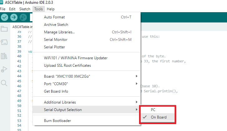
On the XMC boards, two kinds of serial outputs are possible, namely:
SERIAL DEBUG (via PC)
SERIAL ONBOARD
If these two outputs share the same instance of the internal USIC channel, only one of the two could be used at a given time. The selection can be made via the Tools menu as shown in the picture below.
This is generally the case for most of the XMC boards. However, for boards such as the xmc4200-platform2go and the xmc4700-relax, both the serial output modes are simultaneously active and neednot be selected or enabled from the menu.
Note: Please note that the sketch must be recompiled when a different serial output is selected.
For advanced users The build flag -DSERIAL_HOSTPC must be used for the serial output interface via PC and the build flag -DSERIAL_ONBOARD must be used for serial output through the onboard TX and RX pins