Supported Boards
The following XMC microcontroller boards are supported by XMC for Arduino:
Picture |
Board Name |
MCU |
Form Factor |
|---|---|---|---|

|
XMC1100 |
Arduino Uno |
|
|
XMC1302 |
Proprietary |
|

|
XMC1404 |
Shield2Go |
|
|
XMC1402 |
Arduino Uno |
|

|
KIT_XMC47_RELAX variants |
XMC4700 |
Arduino Uno |
Note
For all Kit 2Go or MS 2Go sensor boards please select KIT_XMC_2GO_XMC1100_V1 in the Arduino IDE.
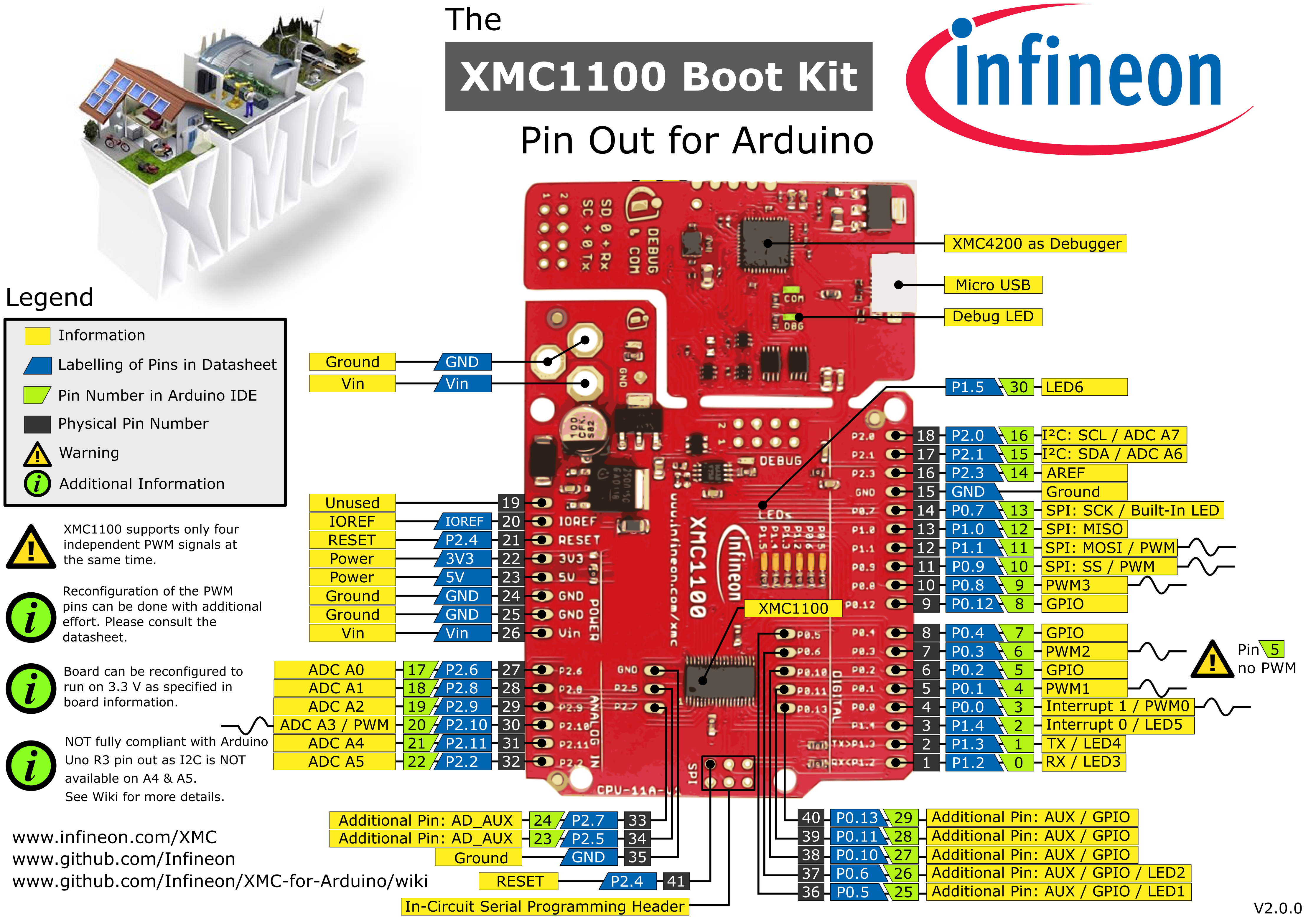
KIT_XMC11_BOOT_001
The KIT_XMC11_BOOT_001 board consists of a XMC1100 microcontroller with a debugger implemented by a XMC4200 microcontroller. The board shares the same power supply and board shape as other boards for Arduino.
Pinout Diagram
Please note that Arduino pin number 16 & 22 (SCL & A5) and Arduino pin number 15 & 21 (SDA & A4) are not connected with each other nor share the same pins/resources. This is different from the original Arduino UNO Rev3 implementation.
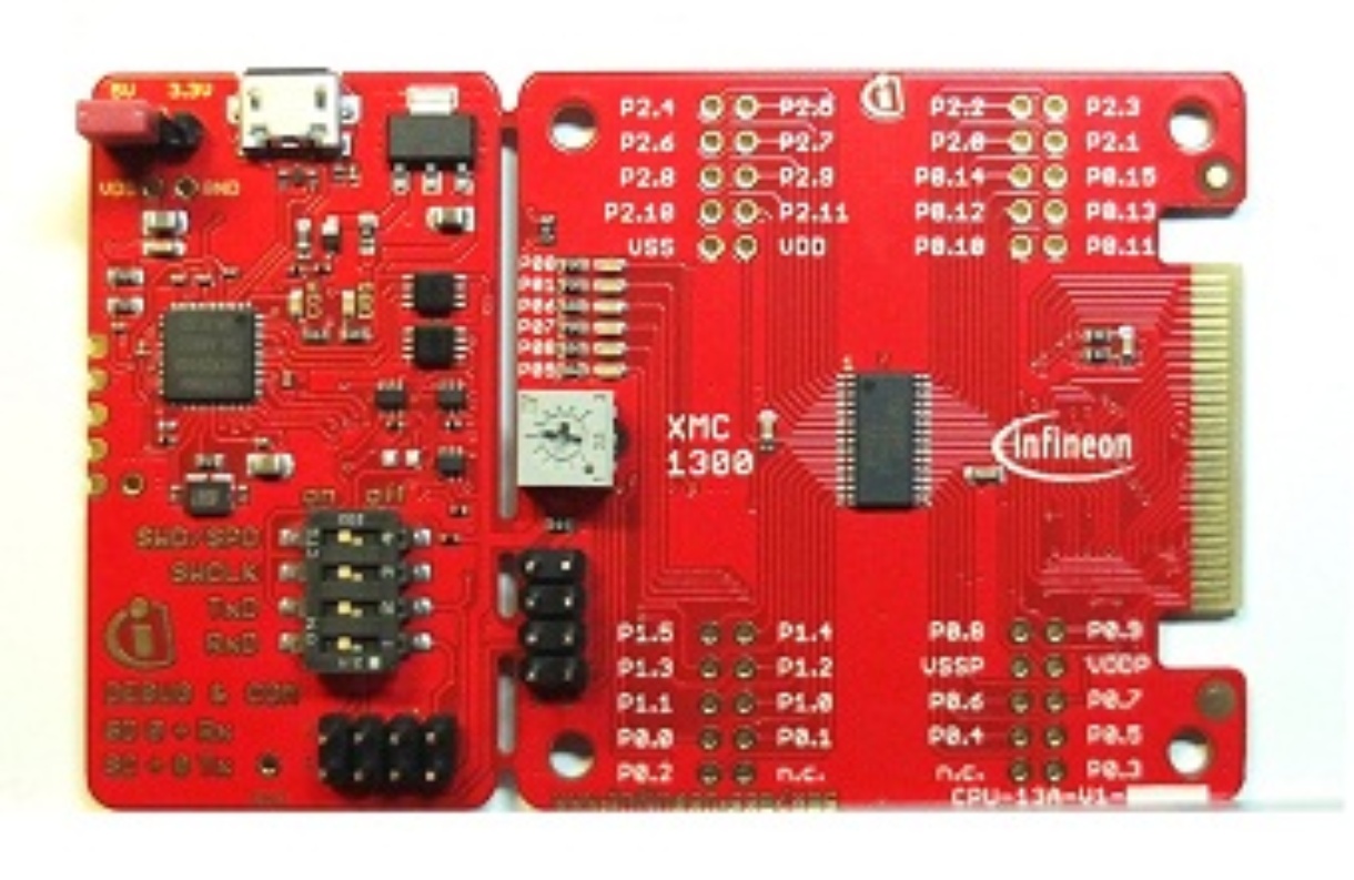
KIT_XMC13_BOOT_001
The KIT_XMC13_BOOT_001 features a XMC1302 microcontroller in TSSOP-38 with 200KB flash and detachable SEGGER J-Link.
Known Issues
Serial Communication Garbled Output
Some board versions may display garbled characters in serial output. To resolve this:
Update J-Link firmware to the latest version. J-Link-Firmware
Reduce baud rate if your application allows (e.g., from 115200 to 9600)
KIT_XMC14_2GO
The KIT_XMC14_2GO provides an easy way to evaluate almost all capabilities of the XMC1400 microcontroller. The kit is powered via USB, interfaces to other Infineon sensor boards and provides multiple interfaces including a CAN bus. The software development is supported via ModusToolbox™ and the Arduino IDE.
Pinout Diagram
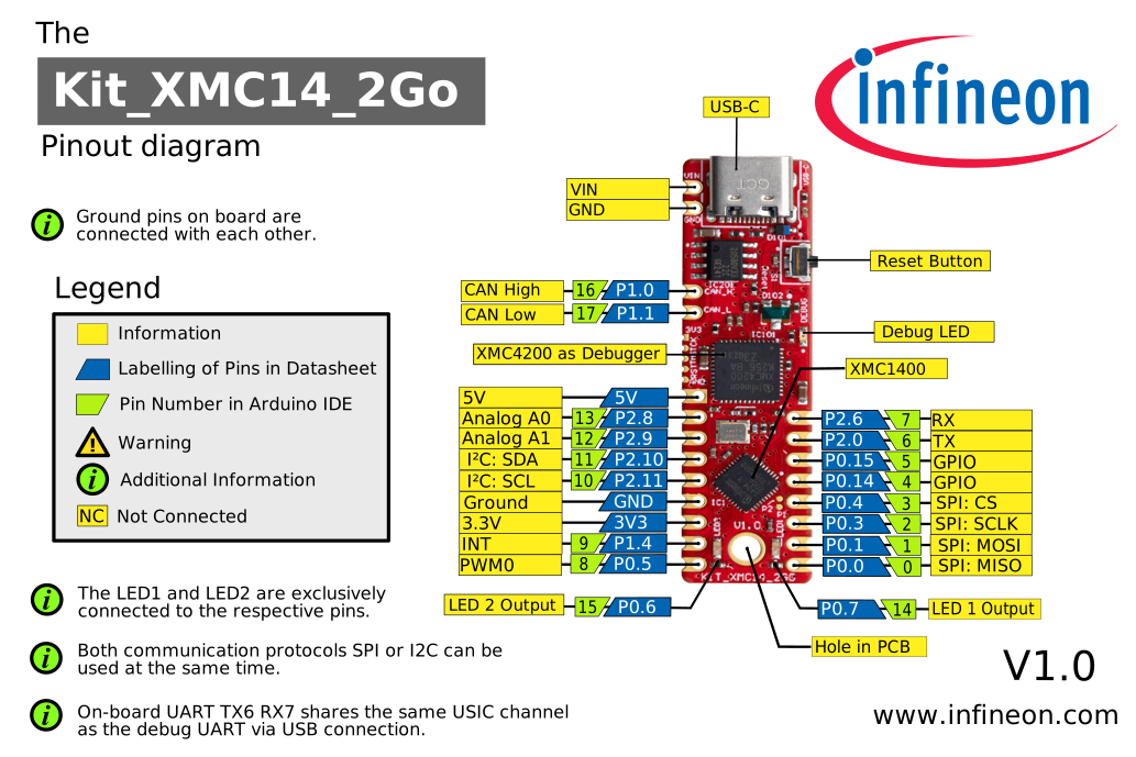
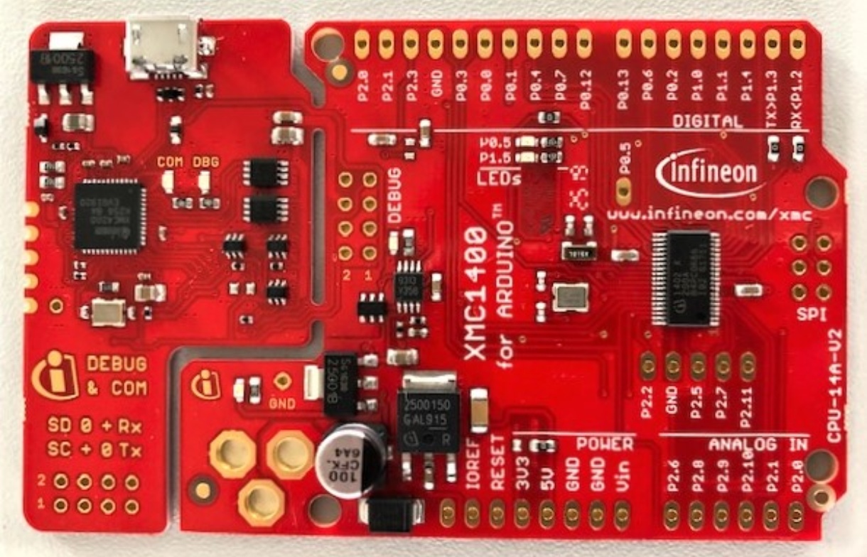
KIT_XMC1400_ARDUINO
The KIT_XMC1400_ARDUINO consists of a XMC1400 microcontroller with a debugger implemented by a XMC4200 microcontroller. The board shares the same power supply and board shape as other boards for Arduino.
Pinout Diagram
Please note that pins P1.4 and P0.5 are swapped on the board and are not consistent with the silkscreen. As a result, interrupt 0 INT0
occurs as Arduino pin 25 and interrupt 1 INT1 is located at Arduino pin 3. This is different from the original
Arduino UNO Rev3 implementation. Please look at the pinout diagram for more information.

KIT_XMC47_RELAX
Supported Variants
The KIT_XMC47_RELAX board variants consists of a XMC4700 microcontroller with a debugger implemented by a XMC4200 microcontroller. Please note that there exist versions with 5V and 3.3V. Please be careful which version you have and use with your respective shields. The one described here is the 5V version as this one is compatible with Arduino shields designed for 5V systems.
Pinout Diagram
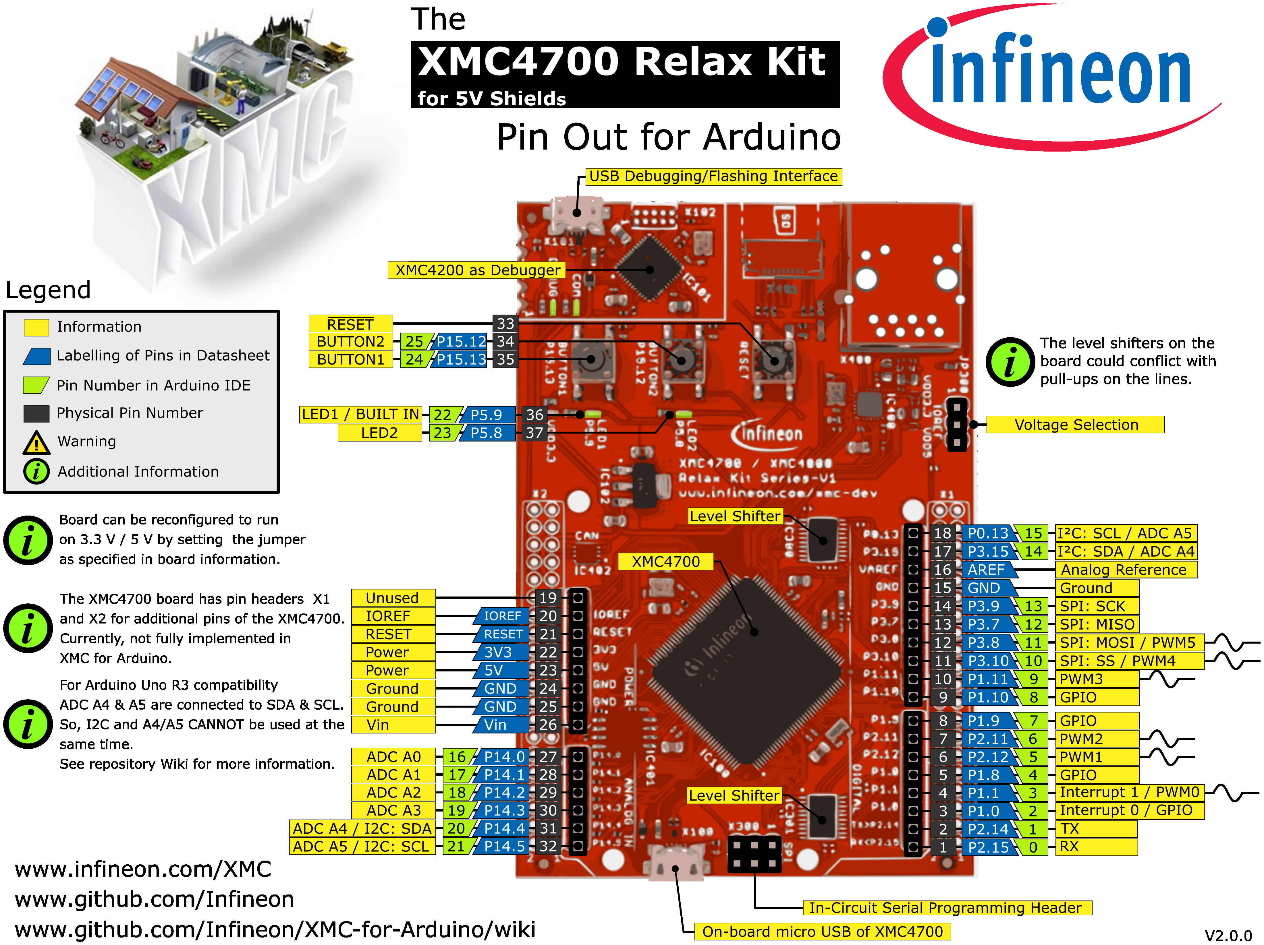
Please note that Arduino pin number 15 & 21 (SCL & A5) and Arduino pin number 14 & 20 (SDA & A4) are connected with each other
on the board itself. If you want to use them check out the subsection Connected I2S and Analog pins.
Connected I2S and Analog pins
For the KIT_XMC47_RELAX the Arduino pin number 15 & 21 (SCL & A5) and Arduino
pin number 14 & 20 (SDA & A4) are connected with each other on the board itself. Although they are different physical pins of the microcontroller,
they are connected with each other on the board to comply with the original Arduino UNO Rev3 pin connections. This influences analog measurements on
A4 and A5 if you are using I2C simultaneously. Details of the connection can also be found in the schematics in the user manual of the board here: KIT_XMC47_RELAX user manual.
The user manual shows on:
Page 11 details the 3.3V signals on connectors
X1andX2(figure 7) including ADC channelsPage 12 below figure 8 details analog input specifications
A workaround is to set the I2C pins to output open drain via pinMode(<pinNumber>, OUTPUT_OPENDRAIN); and writing a HIGH afterwards via digitalWrite(<pinNumber>, HIGH);
to turn it off if you want to use the analog pins (but then I2C cannot be used anymore). Tri-state via pinMode(<pinNumber>, XMC_GPIO_MODE_INPUT_TRISTATE); is also possible,
but the open drain method is preferable. These functions are using the pin mode definitions from the XMC Peripheral Library defined
here.
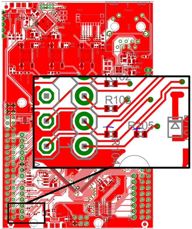
You can also cut the physical connection on the board itself.
For the KIT_XMC47_RELAX cut the blue routes on the back side of the PCB as indicated here:
Legacy Microcontroller Boards
Supported until |
Board Name |
MCU |
Form Factor |
|---|---|---|---|
still |
XMC1100 |
Shield2Go |
|
v1.7.0 |
XMC1100 & IFX9201 |
Shield2Go |
|
v1.7.0 |
XMC1300 |
Proprietary |
|
v3.x |
XMC4200 |
Arduino Uno, Shield2Go, mikroBUS |
|
v3.x |
XMC4400 |
Arduino Uno, Shield2Go, mikroBUS |
|
v1.7.0 |
XMC4700 |
Proprietary |
KIT_XMC_2GO_XMC1100_V1
Replaced by KIT_XMC14_2GO
The XMC1100 2Go board consists of a XMC1100 microcontroller with a debugger implemented by a XMC4200 microcontroller.
Pinout Diagram
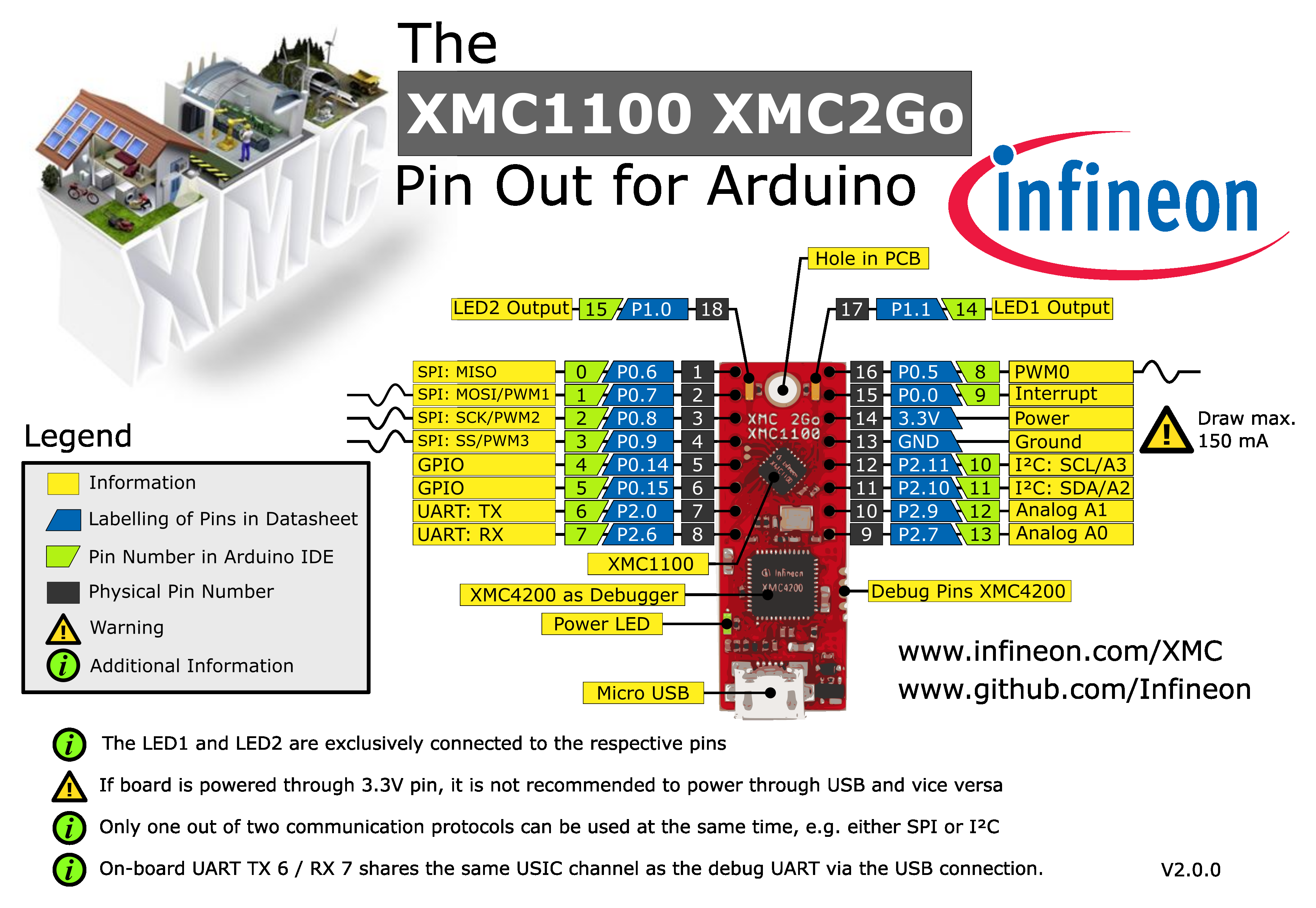
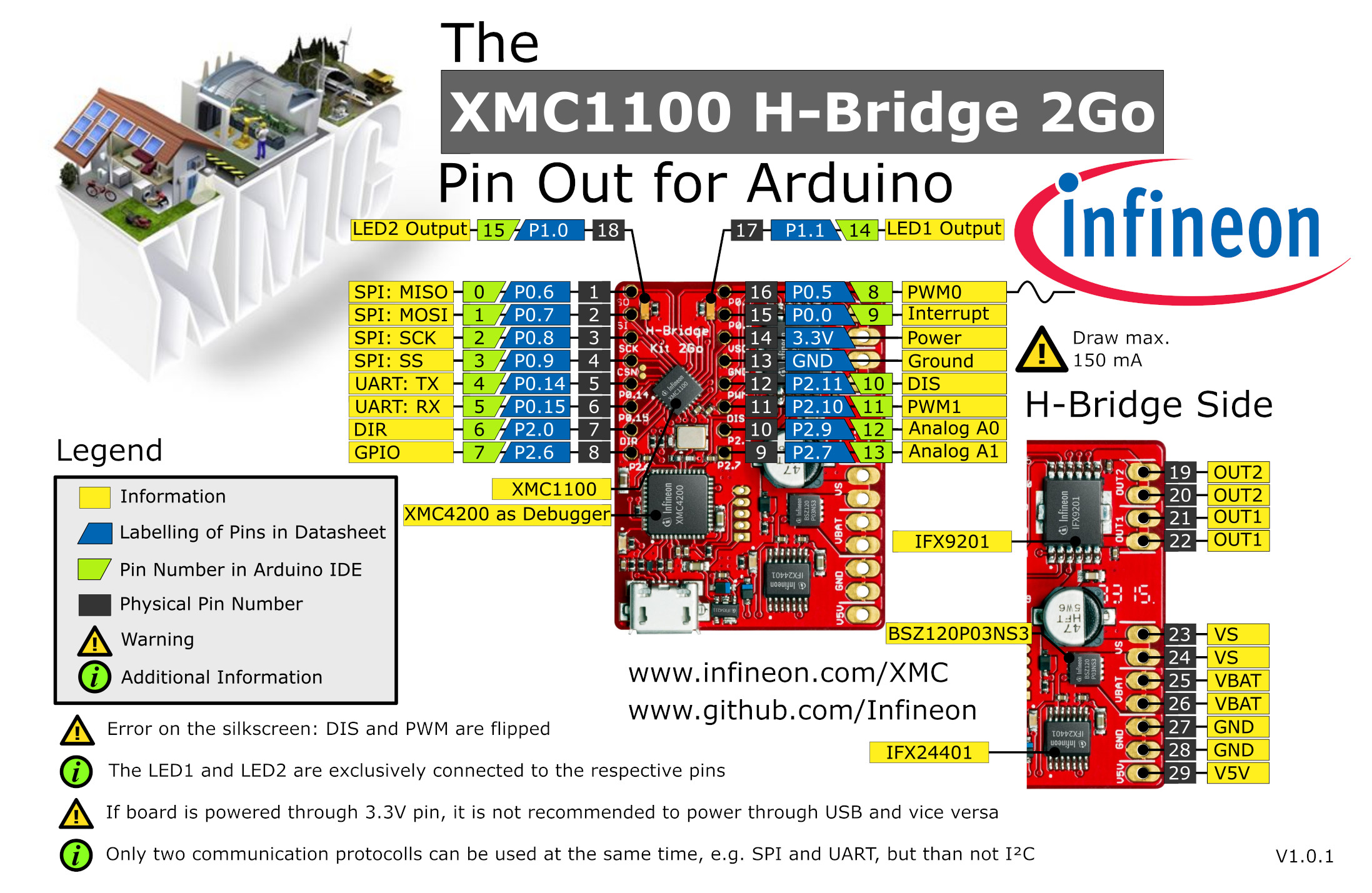
H-BRIDGE KIT 2GO
Name in Arduino IDE:
XMC1100 H-Bridge 2Go
The XMC1100 2Go board consists of a XMC1100 microcontroller with a debugger implemented by a XMC4200 microcontroller.
Pinout Diagram
XMC1300 Sense2GoL
Name in Arduino IDE:
XMC1300 Sense2GoL
24 GHz sensor development kit utilizing Infineon BGT24LTR11 RF transceiver and XMC1300 32-bit ARM® Cortex®-M0 MCU series.
KIT_XMC_PLT2GO_XMC4200
Name in Arduino IDE:
XMC4200 Platform 2GO
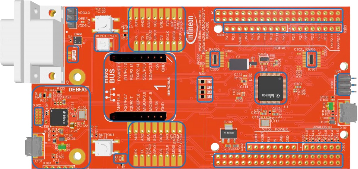
The XMC4200 Platform 2Go evaluation board consists of a XMC4200 microcontroller with a debugger implemented by a XMC4200 microcontroller. Please note that there exist versions with 5V and 3.3V. Please be careful which version you have and use with your respective shields. The one described here is the 5V version as this one is compatible with Arduino shields designed for 5V systems. This kit is equipped with an ARM® Cortex®-M4 based XMC4200 microcontroller with on-board debugger, Ethernet, CAN and footprints for Arduino, MikroBUS and Shield2Go form factors.
Pinout Diagram
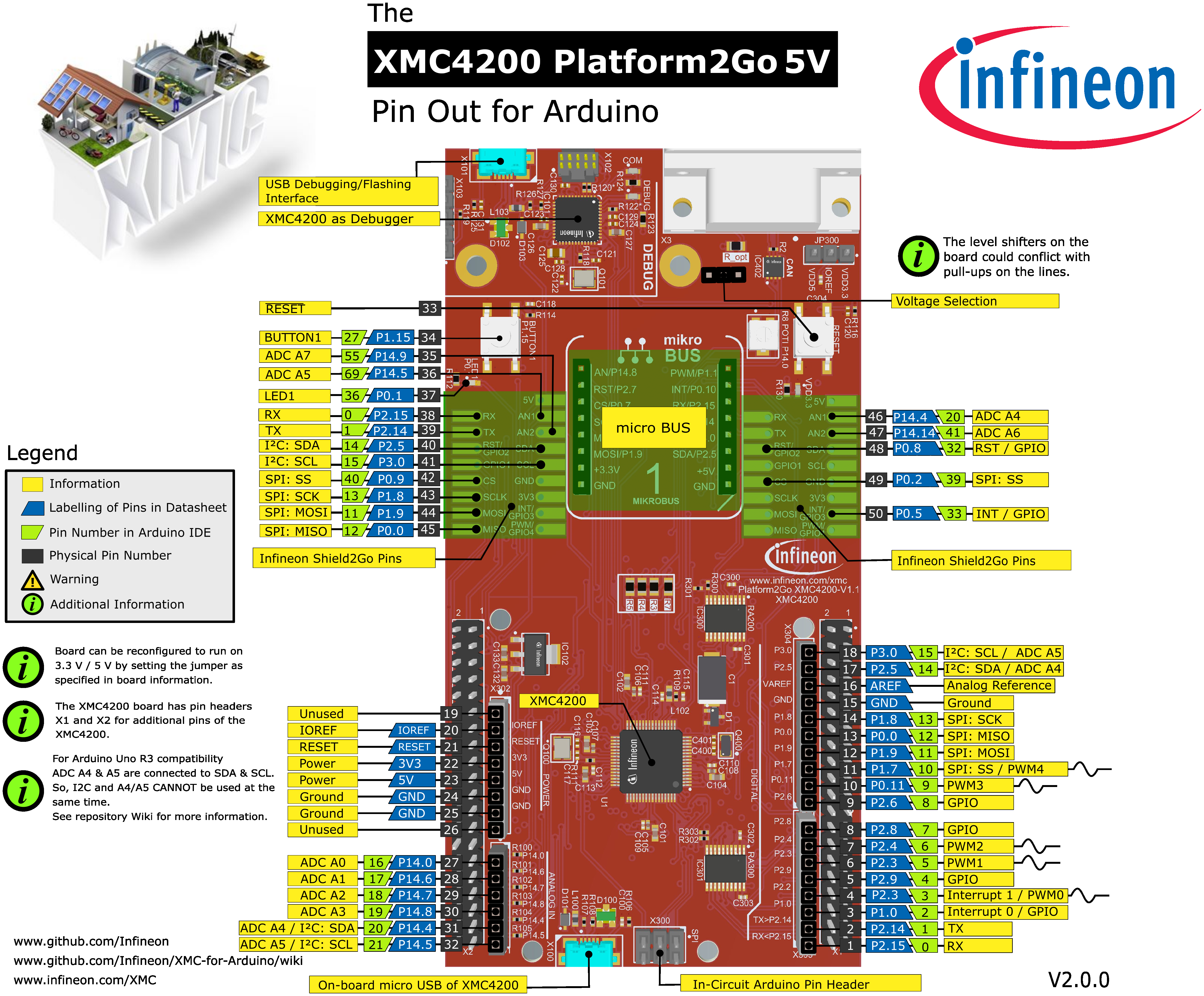
Please note that Arduino pin number 15 & 21 (SCL & A5) and Arduino pin number 14 & 20 (SDA & A4) are connected with each other
on the board itself. If you want to use them check out the subsection Connected I2S and Analog pins.
KIT_XMC_PLT2GO_XMC4400
Name in Arduino IDE:
XMC4400 Platform 2GO
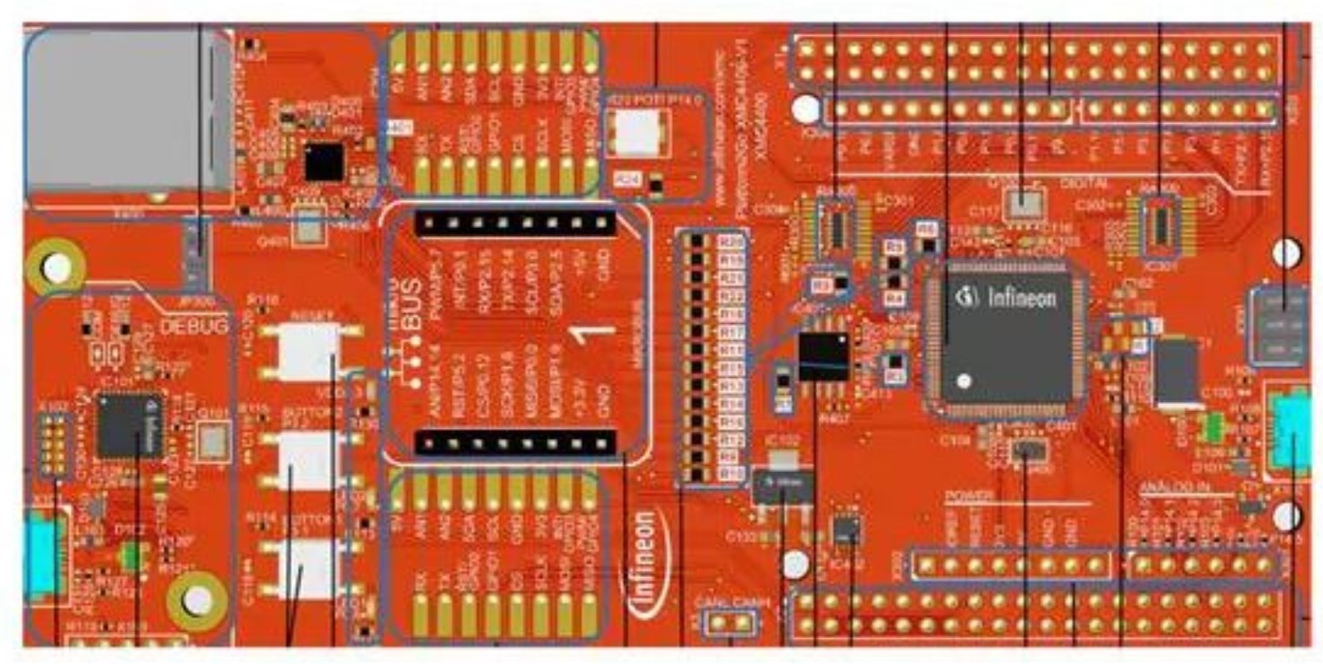
The XMC4400 Platform 2Go evaluation board consists of a XMC4400 microcontroller with a debugger implemented by a XMC4200 microcontroller. Please note that there exist versions with 5V and 3.3V. Please be careful which version you have and use with your respective shields. The one described here is the 5V version as this one is compatible with Arduino shields designed for 5V systems. This kit is equipped with an ARM® Cortex®-M4 based XMC4400 microcontroller with on-board debugger, Ethernet, CAN and footprints for Arduino, MikroBUS and Shield2Go form factors.
Pinout Diagram
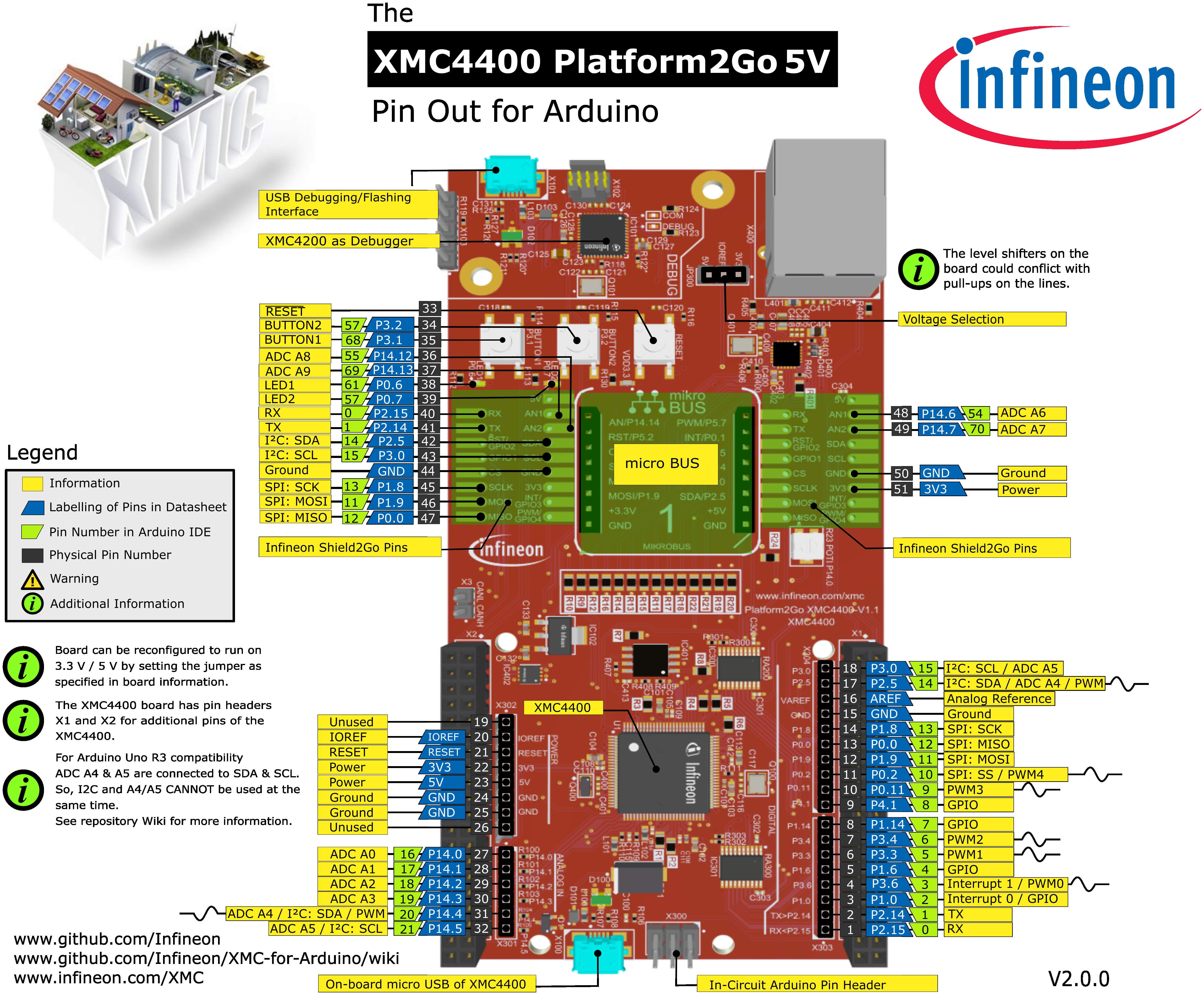
Please note that Arduino pin number 15 & 21 (SCL & A5) and Arduino pin number 14 & 20 (SDA & A4) are connected with each other
on the board itself. If you want to use them check out the subsection Connected I2S and Analog pins.
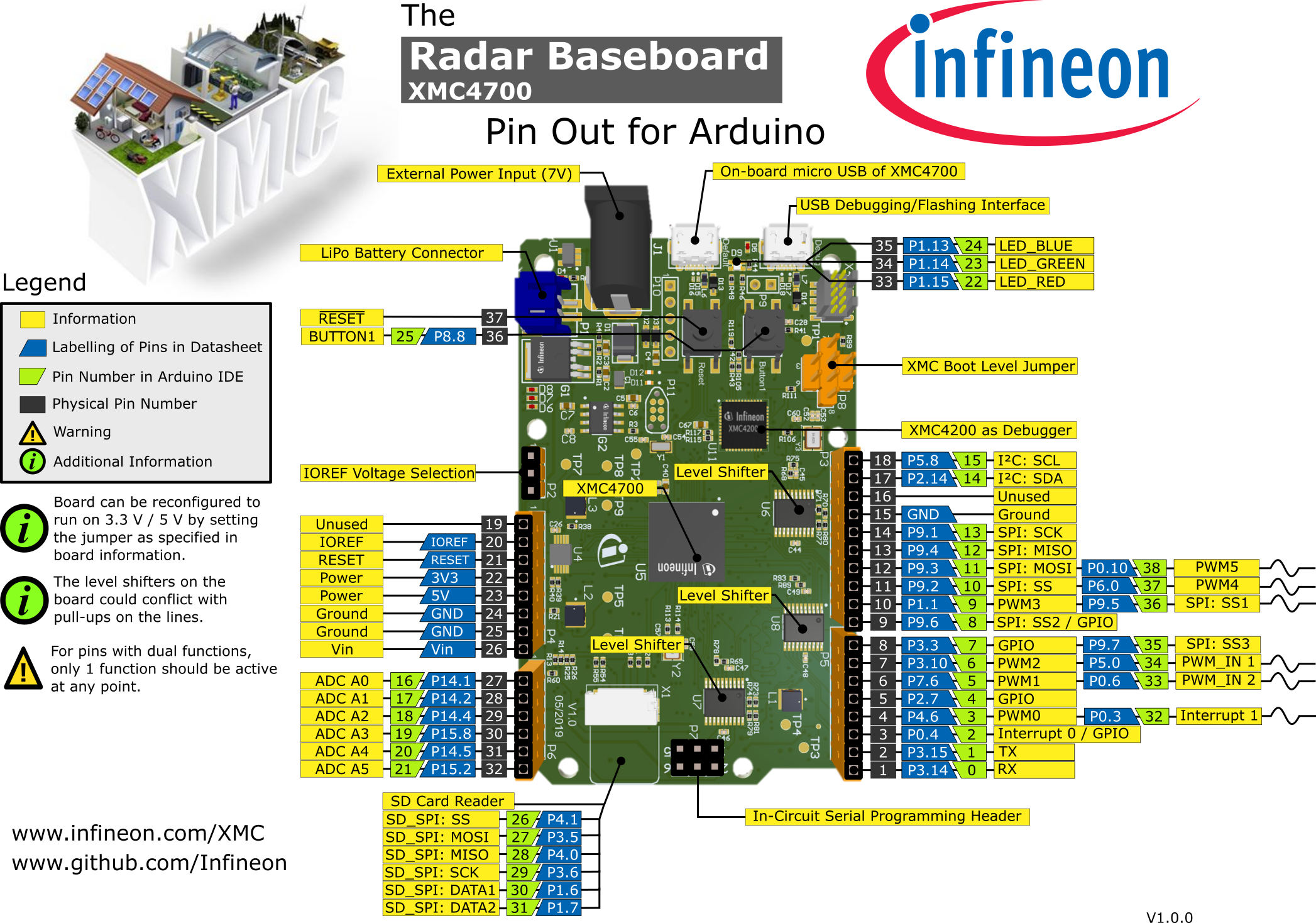
XMC4700 Radar Baseboard
Name in Arduino IDE:
XMC4700 Radar Baseboard
The Sense2GoL Pulse radar system is a demo platform for Infineon’s 24GHz BGT24LTR11 radar transceiver. The Sense2GoL Pulse consists of two boards – the microcontroller board with the XMC4700 (RADAR BB XMC4700) and a radar frontend board (BGT24LTR11 Shield), which features a 4x1 array antenna for the transmitter and receiver sections. It is shielded with a metal cover and absorber material to get the best RF performance.
Pinout Diagram